-
The www2.cesm.ucar.edu website is currently down for maintenance
You are using an out of date browser. It may not display this or other websites correctly.
You should upgrade or use an alternative browser.
You should upgrade or use an alternative browser.
Lower boundary conditions (differences between CLM4.5 and CLM5)
- Thread starter wvsi3w
- Start date
- Status
- Not open for further replies.
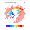
Thank you @oleson for your response,Your last plot (ALT23SL_3.5_unmodified.png) looks pretty much like I would expect. Here is a plot of ALTMAX for northern polar regions for the default soil layer model forced with GSWP3 atm.
View attachment 5398
So based on this plot which shows values below 4m, I think I should change my color bar to see changes in values below a certain meter (like 4m in this plot) because variation in ALT is only important above a certain latitude.
For my first question (regarding the 20SL_8.5_DG soil layer structure which resulted in 193m for ALT in lower latitudes), do you think there is a missing parameter here in the process of simulation, some option that I might have forgotten to include in the simulation (some XML thing, like turning on bedrock?). I don't know why that happened because in the code it clearly adds 10 bedrock layers and doesn't add to the active part of the soil.
This part is the most important question I encountered because if I don't get why that happened after I modified the 23SL_3.5 soil layer structure I would probably end up with the same results for it as I got from 20SL_8.5_DG.
OK, I realized now that ALT itself doesn't mean active soil or just soil layer only. It can be either soil or bedrock. "Active" means that it is not permafrost, i.e. that at some point during the year, it is not frozen.Thank you @oleson for your response,
So based on this plot which shows values below 4m, I think I should change my color bar to see changes in values below a certain meter (like 4m in this plot) because variation in ALT is only important above a certain latitude.
For my first question (regarding the 20SL_8.5_DG soil layer structure which resulted in 193m for ALT in lower latitudes), do you think there is a missing parameter here in the process of simulation, some option that I might have forgotten to include in the simulation (some XML thing, like turning on bedrock?). I don't know why that happened because in the code it clearly adds 10 bedrock layers and doesn't add to the active part of the soil.
This part is the most important question I encountered because if I don't get why that happened after I modified the 23SL_3.5 soil layer structure I would probably end up with the same results for it as I got from 20SL_8.5_DG.
Sorry for the misunderstanding.
I would modify the 23SL_3.5 to reach 500m depth (100m increments) and let you know if I have any questions.
Thanks.
Hello,
To increase the lower boundary in CLM5 I did all of the modifications to the codes based on the instruction of this paper (Lower boundary conditions improvement in CLM4.5) which is for CLM4.5. However, some of the files uploaded in the article link are probably missing some lines (?).
For example, in the README file in that link, they mention "Added flxdat to the list of variables used from clm_varctl", but I dont see flxdat in the iniTimeConst file uploaded there. I already added this to my CLM5 code but I don't know if it is correct.
Moreover, eflx_bot is not there in the iniTimeConst file of clm4.5 but it is stated that eflx_bot is defined as a local pointer, which is then assigned to a subtype component.
I think that file is not the actual file. I already added this part to my CLM5 code with the help of GPT4 but I dont know if it is correct (attached here).
Also, the "allocate(bhf" and "eflx_bot => col%eflx_bot" are not in the clm4.5 iniTimeConst file, but they are mentioned in the README file of that paper and I added them to my file my way (which again I don't know if I did it right or not).
I am seeking guidance from the experts here to modify these CLM5 codes.
Thanks for your support (@oleson).
Attachments
Thank you @slevis for your response.We expect you, as a research scientist, to figure out things like this through trial and error. Unfortunately we do not provide support for what you're asking.
I will let you know if my try and error process resulted in any presentable outputs. For now I will stick to the bottom boundary modification runs and skip the bottom heat flux option.
Best wishes
Greetings,
I have tested the CLM5 with this new depth modification and it did run as I wanted.
Because I want to work with permafrost, and the "23SL_3.5m" is a good choice for this matter (Soil layer structure that starts with standard exponential and then has several evenly spaced layers, then finishes off exponential. This allows the upper soil to behave as standard, but then continues with higher resolution to a deeper depth, so that, for example, permafrost dynamics are not lost due to an inability to resolve temperature, moisture, and biogeochemical dynamics at the base of the active layer).
So I modified it, and the followings are the details:
inside initVerticalMod file:
scalez = 0.029_r8 ! Soil layer thickness discretization (m) (changed it from 0.025 to 0.029)
And,
in clm_varpar file (added 5 more layers to the bottom exponential layers):
And, added the "23SL_3.5m_D500" to the namelist definition file:
I was wondering if you think there are any issues to this modification. Beacuse as I was reading other papers that did this kind of bottom boundary modification they went through a lot of change in several files and lines and variables which for example one of them increased the thick_equal value and the other added another set of formula for 20SL_8.5 soil layer so that it creates a bunch of equal deep layers at the bottom. The thing I did is that I added 5 more exponential layers to the bottom of 23SL_3.5 soil layer and I increased the scalez value by 4mm (0.029 modified - 0.025 default) because this way I would have about the same depth of soil at the 23rd layer (before modification it was 3.6m now it is ~3.7m), so I kinda saved the structure of the upper soil layer as it was and just increased the lower levels exponentially.
What do you think?
P.S. The ALT and ALTMAX values are truly 500m for a test run, which means it worked. But still knowing your POV is beneficial.
I have tested the CLM5 with this new depth modification and it did run as I wanted.
Because I want to work with permafrost, and the "23SL_3.5m" is a good choice for this matter (Soil layer structure that starts with standard exponential and then has several evenly spaced layers, then finishes off exponential. This allows the upper soil to behave as standard, but then continues with higher resolution to a deeper depth, so that, for example, permafrost dynamics are not lost due to an inability to resolve temperature, moisture, and biogeochemical dynamics at the base of the active layer).
So I modified it, and the followings are the details:
inside initVerticalMod file:
scalez = 0.029_r8 ! Soil layer thickness discretization (m) (changed it from 0.025 to 0.029)
And,
Code:
else if ( soil_layerstruct == '23SL_3.5m_D500' )then
       do j = 1, toplev_equalspace
          zsoi(j) = scalez*(exp(0.5_r8*(j-0.5_r8))-1._r8)    !node depths
       enddo

       do j = toplev_equalspace+1,toplev_equalspace + nlev_equalspace
          zsoi(j) = zsoi(j-1) + thick_equal
       enddo

       do j = toplev_equalspace + nlev_equalspace +1, nlevgrnd
          zsoi(j) = scalez*(exp(0.5_r8*((j - nlev_equalspace)-0.5_r8))-1._r8) + nlev_equalspace * thick_equal
       enddo

       dzsoi(1) = 0.5_r8*(zsoi(1)+zsoi(2))             !thickness b/n two interfaces
       do j = 2,nlevgrnd-1
          dzsoi(j)= 0.5_r8*(zsoi(j+1)-zsoi(j-1))
       enddo
       dzsoi(nlevgrnd) = zsoi(nlevgrnd)-zsoi(nlevgrnd-1)

       zisoi(0) = 0._r8
       do j = 1, nlevgrnd-1
       zisoi(j) = 0.5_r8*(zsoi(j)+zsoi(j+1))         !interface depths
       enddo
       zisoi(nlevgrnd) = zsoi(nlevgrnd) + 0.5_r8*dzsoi(nlevgrnd)
in clm_varpar file (added 5 more layers to the bottom exponential layers):
Code:
    else if ( soil_layerstruct == '23SL_3.5m_D500' ) then
       nlevsoi     =  8  + nlev_equalspace
       nlevgrnd    =  20 + nlev_equalspace
And, added the "23SL_3.5m_D500" to the namelist definition file:
Code:
<entry id="soil_layerstruct" type="char*16" category="clm_physics"
       group="clm_inparm" valid_values="10SL_3.5m,23SL_3.5m,49SL_10m,20SL_8.5m,23SL_3.5m_D500" >
10SL_3.5m    = standard CLM4 and CLM4.5 version
23SL_3.5m    = more vertical layers for permafrost simulations
49SL_10m     = 49 layer soil column, 10m of soil, 5 bedrock layers
20SL_8.5m    = 20 layer soil column, 8m of soil, 5 bedrock layers
23SL_3.5m_D500 = 23 layer soil column, 3.7m of soil, extended to 500m depth
</entry>
I was wondering if you think there are any issues to this modification. Beacuse as I was reading other papers that did this kind of bottom boundary modification they went through a lot of change in several files and lines and variables which for example one of them increased the thick_equal value and the other added another set of formula for 20SL_8.5 soil layer so that it creates a bunch of equal deep layers at the bottom. The thing I did is that I added 5 more exponential layers to the bottom of 23SL_3.5 soil layer and I increased the scalez value by 4mm (0.029 modified - 0.025 default) because this way I would have about the same depth of soil at the 23rd layer (before modification it was 3.6m now it is ~3.7m), so I kinda saved the structure of the upper soil layer as it was and just increased the lower levels exponentially.
What do you think?
P.S. The ALT and ALTMAX values are truly 500m for a test run, which means it worked. But still knowing your POV is beneficial.
I have attached the related files here.Greetings,
I have tested the CLM5 with this new depth modification and it did run as I wanted.
Because I want to work with permafrost, and the "23SL_3.5m" is a good choice for this matter (Soil layer structure that starts with standard exponential and then has several evenly spaced layers, then finishes off exponential. This allows the upper soil to behave as standard, but then continues with higher resolution to a deeper depth, so that, for example, permafrost dynamics are not lost due to an inability to resolve temperature, moisture, and biogeochemical dynamics at the base of the active layer).
So I modified it, and the followings are the details:
inside initVerticalMod file:
scalez = 0.029_r8 ! Soil layer thickness discretization (m) (changed it from 0.025 to 0.029)
And,
Code:else if ( soil_layerstruct == '23SL_3.5m_D500' )then do j = 1, toplev_equalspace zsoi(j) = scalez*(exp(0.5_r8*(j-0.5_r8))-1._r8) !node depths enddo do j = toplev_equalspace+1,toplev_equalspace + nlev_equalspace zsoi(j) = zsoi(j-1) + thick_equal enddo do j = toplev_equalspace + nlev_equalspace +1, nlevgrnd zsoi(j) = scalez*(exp(0.5_r8*((j - nlev_equalspace)-0.5_r8))-1._r8) + nlev_equalspace * thick_equal enddo dzsoi(1) = 0.5_r8*(zsoi(1)+zsoi(2)) !thickness b/n two interfaces do j = 2,nlevgrnd-1 dzsoi(j)= 0.5_r8*(zsoi(j+1)-zsoi(j-1)) enddo dzsoi(nlevgrnd) = zsoi(nlevgrnd)-zsoi(nlevgrnd-1) zisoi(0) = 0._r8 do j = 1, nlevgrnd-1 zisoi(j) = 0.5_r8*(zsoi(j)+zsoi(j+1)) !interface depths enddo zisoi(nlevgrnd) = zsoi(nlevgrnd) + 0.5_r8*dzsoi(nlevgrnd)
in clm_varpar file (added 5 more layers to the bottom exponential layers):
Code:else if ( soil_layerstruct == '23SL_3.5m_D500' ) then nlevsoi = 8 + nlev_equalspace nlevgrnd = 20 + nlev_equalspace
And, added the "23SL_3.5m_D500" to the namelist definition file:
Code:<entry id="soil_layerstruct" type="char*16" category="clm_physics" group="clm_inparm" valid_values="10SL_3.5m,23SL_3.5m,49SL_10m,20SL_8.5m,23SL_3.5m_D500" > 10SL_3.5m = standard CLM4 and CLM4.5 version 23SL_3.5m = more vertical layers for permafrost simulations 49SL_10m = 49 layer soil column, 10m of soil, 5 bedrock layers 20SL_8.5m = 20 layer soil column, 8m of soil, 5 bedrock layers 23SL_3.5m_D500 = 23 layer soil column, 3.7m of soil, extended to 500m depth </entry>
I was wondering if you think there are any issues to this modification. Beacuse as I was reading other papers that did this kind of bottom boundary modification they went through a lot of change in several files and lines and variables which for example one of them increased the thick_equal value and the other added another set of formula for 20SL_8.5 soil layer so that it creates a bunch of equal deep layers at the bottom. The thing I did is that I added 5 more exponential layers to the bottom of 23SL_3.5 soil layer and I increased the scalez value by 4mm (0.029 modified - 0.025 default) because this way I would have about the same depth of soil at the 23rd layer (before modification it was 3.6m now it is ~3.7m), so I kinda saved the structure of the upper soil layer as it was and just increased the lower levels exponentially.
What do you think?
P.S. The ALT and ALTMAX values are truly 500m for a test run, which means it worked. But still knowing your POV is beneficial.
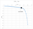
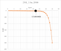
Also the plots and tables of this modification are like this:

vs

which shows a slight change in the last soil layer depth. So, I added 5 exponential layers to the bottom of this structure + 4mm increase of the "scalez" variable (which is the layer thickness discretization value), and kept the top layers almost intact so that they don't change alot and remain close to initial form that was defined for permafrost region = 500m of depth.
| 23SL_3.5m | layers | 1 | 2 | 3 | 4 | 5 | 6 | 7 | 8 | 9 | 10 | 11 | 12 | 13 | 14 | 15 | 16 | 17 | 18 | 19 | 20 | 21 | 22 | 23 | 24 | 25 | 26 | 27 | 28 | 29 | 30 |
| depth | 0.01 | 0.03 | 0.06 | 0.12 | 0.21 | 0.37 | 0.57 | 0.77 | 0.97 | 1.17 | 1.37 | 1.57 | 1.77 | 1.97 | 2.17 | 2.37 | 2.57 | 2.77 | 2.97 | 3.17 | 3.37 | 3.62 | 4.04 | 4.73 | 5.86 | 7.74 | 10.83 | 15.93 | 24.33 | 38.18 |
scalez=0.025
| 23SL_3.5m_D500 | layers | 1 | 2 | 3 | 4 | 5 | 6 | 7 | 8 | 9 | 10 | 11 | 12 | 13 | 14 | 15 | 16 | 17 | 18 | 19 | 20 | 21 | 22 | 23 | 24 | 25 | 26 | 27 | 28 | 29 | 30 | 31 | 32 | 33 | 34 | 35 |
| depth | 0.01 | 0.03 | 0.07 | 0.14 | 0.25 | 0.42 | 0.62 | 0.82 | 1.02 | 1.22 | 1.42 | 1.62 | 1.82 | 2.02 | 2.22 | 2.42 | 2.62 | 2.82 | 3.02 | 3.22 | 3.42 | 3.72 | 4.20 | 5.00 | 6.32 | 8.50 | 12.08 | 17.99 | 27.74 | 43.81 | 70.30 | 113.97 | 185.98 | 304.70 | 500.44 |
scalez=0.029
Attachments
For this approach I modified the 9 Fortran Codes this way.Hello,
To increase the lower boundary in CLM5 I did all of the modifications to the codes based on the instruction of this paper (Lower boundary conditions improvement in CLM4.5) which is for CLM4.5. However, some of the files uploaded in the article link are probably missing some lines (?).
For example, in the README file in that link, they mention "Added flxdat to the list of variables used from clm_varctl", but I dont see flxdat in the iniTimeConst file uploaded there. I already added this to my CLM5 code but I don't know if it is correct.
Moreover, eflx_bot is not there in the iniTimeConst file of clm4.5 but it is stated that eflx_bot is defined as a local pointer, which is then assigned to a subtype component.
I think that file is not the actual file. I already added this part to my CLM5 code with the help of GPT4 but I dont know if it is correct (attached here).
Also, the "allocate(bhf" and "eflx_bot => col%eflx_bot" are not in the clm4.5 iniTimeConst file, but they are mentioned in the README file of that paper and I added them to my file my way (which again I don't know if I did it right or not).
I am seeking guidance from the experts here to modify these CLM5 codes.
Thanks for your support (@oleson).
I haven't tested it yet and when it is done I will let you know.
For our reference I attached the 9 files.
These modifications are based on this paper: Lower boundary conditions improvement in CLM4.5
Attachments
- Status
- Not open for further replies.

