Scheduled Downtime
On Tuesday 24 October 2023 @ 5pm MT the forums will be in read only mode in preparation for the downtime. On Wednesday 25 October 2023 @ 5am MT, this website will be down for maintenance and expected to return online later in the morning.
Normal Operations
The forums are back online with normal operations. If you notice any issues or errors related to the forums, please reach out to help@ucar.edu

orography

wickone

Jihan, Sim
New Member
What version of the code are you using?
CESM2.1.3

Describe your problem or question:
I am currently investigating how the topography data is generated in CESM2 and would like to ask a few specific questions to better understand the process. I would greatly appreciate any clarification or references you could provide.
  1. Source DEM Data
    Could you please confirm which digital elevation model (DEM) was used to generate the topography data in CESM2? Was it based on GTOPO30, GMTED2010 (1km or 250m resolution), or another dataset?
  2. Differences in Greenland SGH30 Fields
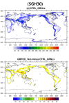
    I have been comparing the following two topography files:
    • fv_1.9x2.5_nc3000_Nsw084_Nrs016_Co120_Fi001_ZR_031819.nc
    • fv_1.9x2.5_nc3000_Nsw084_Nrs016_Co120_Fi001_ZR_GRNL_031819.nc
    • While the filenames differ only by the inclusion of "GRNL", I noticed that the SGH30 field is significantly elevated over Greenland in the GRNL version.Could you explain the reasoning or methodology behind this modification? Was there a scientific justification or specific criterion applied to enhance subgrid-scale topographic variance (SGH30) over Greenland?
  3. Topo Tool Configuration (Topo-NCAR_Topo_2_0_2)
    When generating topography using the Topo-NCAR_Topo_2_0_2 tool, particularly during the bin_to_cube and cube_to_target steps, could you provide details about the specific options or settings used during these stages?

Thank you very much for your time and support. I would greatly appreciate any insights or documentation you can share regarding these topics.
 

pel

New Member
Apologies for the slow reponse.

1. GMTED2010 at 1km resolution.
2. Yes we altered SGH30 over Greenland to improve precipitation and thereby the surface-mass-balance.

Methodology:

Run the topo software twice. Once with correct global settings (60 pt smoothing radius -- Co060 --- and find_rigdes), and another with modified smoothing radius (8 pt smoothing radius -- Co008 -- and no ridges).

2. Run "postproc_mask.py" to merge the two files together. Script here (if you have access to NCAR computers):

/glade/work/aherring/grids/topo_updater/dynamic_atm_topog.arh/postproc/postproc_mask.arhfix.py

a. locate a mask file for the GrIS, which had a hard coded path to: /glade/p/cesm/liwg/cam_dyn_topog_data/greenland_mask_FV1.nc
b. Substitute the SGH30 field in the Co060 file with the SGH field in the Co008 file, where mask=1.

3. See 2.
 
Vote Upvote 0 Downvote

pel

New Member
Regarding item 1:

For some reason, the GMTED2010 dataset appears to be inaccurate over the Antarctic Peninsula. To address this, we incorporated GTOPO30 data for that region. Additional differences between GTOPO30 and GMTED2010 are discussed in Section 3.3 of this paper.
 
Vote Upvote 0 Downvote

wickone

Jihan, Sim
New Member
Regarding item 1:

For some reason, the GMTED2010 dataset appears to be inaccurate over the Antarctic Peninsula. To address this, we incorporated GTOPO30 data for that region. Additional differences between GTOPO30 and GMTED2010 are discussed in Section 3.3 of this paper.
Thank you very much for your kind and detailed response.

Below is the command I used to generate the topography data based on the GMTED2010 dataset at 1 km resolution:

./cube_to_target --grid_descriptor_file='../regression-test-data/fv1.9x2.5.nc' --intermediate_cs_name='../bin_to_cube/GMTED2010_FINAL_v3-ncube3000.nc' --output_grid='fv1.9x2.5' -u 'Peter Hjort Lauritzen, pel@ucar' -q 'output/' --smoothing_scale=200.0 --source_data_identifier='GMTED2010_FINAL_v4' --fine_radius=1 -m T

I tried to match the CESM2 input topography file naming convention when setting the options.
However, I noticed that the resulting SGH30 values from my run are systematically higher than those in the CESM2 input file:

CESM2 input: fv_1.9x2.5_nc3000_Nsw084_Nrs016_Co120_Fi001_ZR_031819.nc

Would you happen to know why this might be the case?

Any insight would be greatly appreciated.
 
Vote Upvote 0 Downvote

wickone

Jihan, Sim
New Member
Apologies for the slow reponse.

1. GMTED2010 at 1km resolution.
2. Yes we altered SGH30 over Greenland to improve precipitation and thereby the surface-mass-balance.

Methodology:

Run the topo software twice. Once with correct global settings (60 pt smoothing radius -- Co060 --- and find_rigdes), and another with modified smoothing radius (8 pt smoothing radius -- Co008 -- and no ridges).

2. Run "postproc_mask.py" to merge the two files together. Script here (if you have access to NCAR computers):

/glade/work/aherring/grids/topo_updater/dynamic_atm_topog.arh/postproc/postproc_mask.arhfix.py

a. locate a mask file for the GrIS, which had a hard coded path to: /glade/p/cesm/liwg/cam_dyn_topog_data/greenland_mask_FV1.nc
b. Substitute the SGH30 field in the Co060 file with the SGH field in the Co008 file, where mask=1.

3. See 2.
Upon closer inspection, I found that the SGH30 field is determined during the bin_to_cube stage rather than in cube_to_target.

However, the namelist for that stage only contains the option to set ncube and nothing else.

It seems to me that the DEM data might be smoothed or otherwise processed before being input into bin_to_cube.
Is that correct?

If so, could you please explain the preprocessing steps applied to the DEM data before it is used?

Thank you very much for your time and clarification.
 
Vote Upvote 0 Downvote
Top